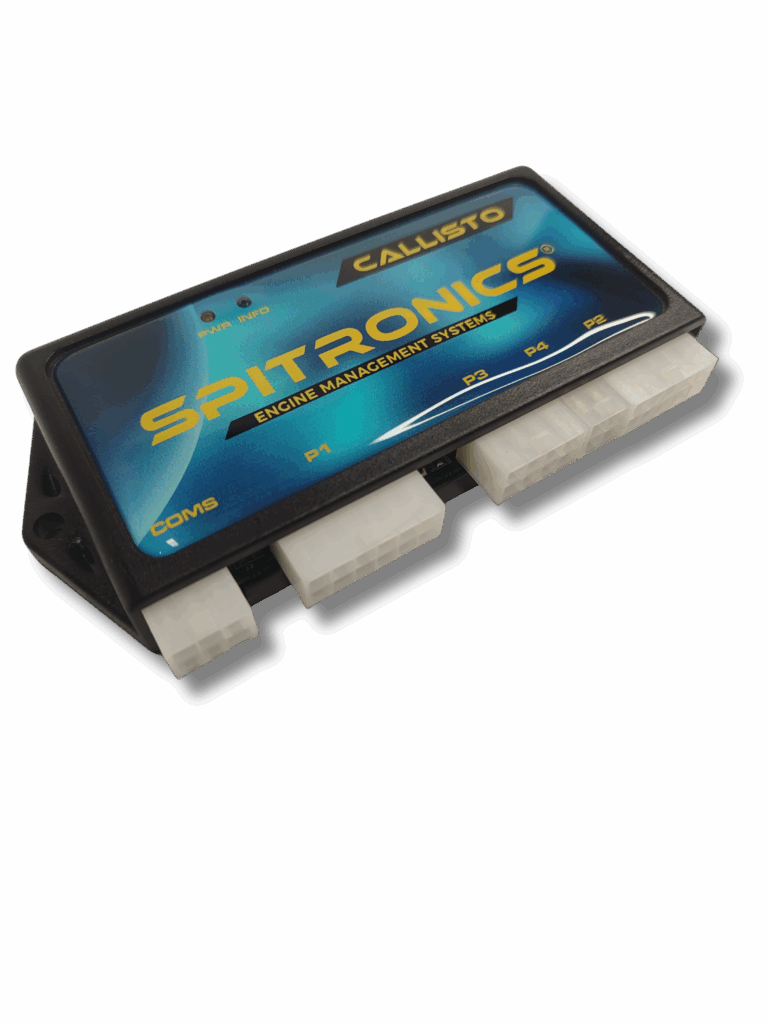
Wiring an aftermarket ECU like a Spitronics unit is a critical process that can make or break your engine management system. One small mistake can cause hours of troubleshooting, poor engine performance, or even damage to components. In this blog post, we’ll cover the most common wiring mistakes during ECU installation and how to avoid them.
1. Improper Grounding
Issue:
Many installation issues stem from poor grounding. If the ECU doesn’t have a solid electrical ground, sensors can read inaccurately, the unit can become unstable, or communication with the laptop may fail.
What to do:
- Ground the ECU directly to the engine block or battery negative.
- Avoid grounding to body panels, bolts with paint or rust, or long thin wires.
- Use a thick, dedicated ground wire (minimum 2.5 mm²).
- Ensure sensor grounds return to the ECU—not to chassis ground.
Learn more in the Spitronics Wiring Manuals.
2. Incorrect Power Source for Switched Ignition (IGN+)
Issue:
The ECU requires a stable 12V IGN+ (switched) power source. Pulling this from the wrong location can cause voltage drops or keep the ECU powered when the ignition is off.
What to do:
- Source IGN+ from a clean ignition circuit that only powers on with the key.
- Avoid piggybacking on circuits for relays, fuel pumps, or lighting.
- Use a relay for switched power if current demand is high.
Check your specific Spitronics ECU model for proper power wiring instructions.
3. Powering the ECU and Injectors from the Same Line Without a Relay
Issue:
Injectors draw significant current. Powering them on the same line as the ECU without isolation can introduce electrical noise or drop voltage under load.
What to do:
- Use separate relays and fuses for injectors, coils, and the ECU.
- Ensure all high-draw components (injectors, fuel pump, coils) are isolated with their own power circuits.
4. Incorrect Sensor Wiring (TPS, MAP, Temp)
Issue:
Mixing up sensor signal, 5V reference, and ground wires can damage the sensor or ECU, or produce unstable readings.
What to do:
- Always verify pinouts from the Spitronics installation manual and the sensor datasheet.
- Never swap signal and power.
- Use shielded wire for signal-critical sensors like crank or cam.
5. Crank & Cam Sensor Signal Noise or Interference
Issue:
Crank and cam signals are sensitive to EMI (electromagnetic interference). Routing these wires next to injectors or coil power can cause signal errors or false triggering.
What to do:
- Use twisted, shielded wire for crank and cam sensors.
- Keep sensor wiring away from ignition coils, high-current lines, and alternator wiring.
- Ground only one end of the shield to the ECU or sensor ground.
6. Shared Grounds Between High Current Loads and the ECU
Issue:
Using a shared ground point for both the ECU and high-draw components (e.g., fuel pump, fan, ignition coils) can introduce voltage fluctuations into the ECU.
What to do:
- Ground the ECU and sensors to a clean, dedicated location.
- High current devices must use separate ground paths directly to chassis or battery negative.
7. Incorrect Fusing
Issue:
Lack of proper fusing can lead to damage or fire in case of a short circuit. Some users overlook fuses entirely or use incorrect amperage.
What to do:
- Fuse every major power supply (ECU, injectors, ignition, fuel pump).
- Use the correct rating: typically 10A for ECU, 15–20A for injectors/coils.
- Place fuses close to the power source (battery or relay).
8. Faulty or Incompatible USB/UART Communication Cable
Issue:
Using a low-quality or incompatible USB-to-UART cable will result in failed communication between the laptop and ECU.
What to do:
- Use the original Spitronics-supplied cable or a known-compatible FTDI-based UART.
- Avoid Prolific or cheap CH340-based converters unless verified working.
- Ensure drivers are properly installed and COM ports configured in the Spitronics Software.
Final Tips
- Label everything. Use heat-shrink or adhesive labels during wiring.
- Double-check polarity before connecting sensors or actuators.
- Use a multimeter to verify power, ground, and signal continuity before powering on the ECU.
- Always follow the official Spitronics wiring diagrams and installation manuals.
Conclusion
Wiring mistakes are the most common cause of issues during Spitronics ECU installations. Taking the time to plan, verify, and wire correctly will save you from hours of frustration and potential damage. If you run into issues, double-check grounds, power supply, and sensor orientation first—they’re often the culprits.


